
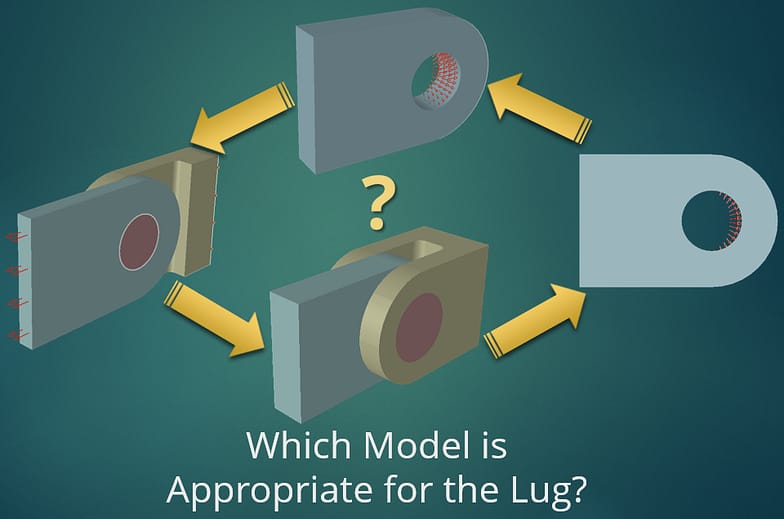
Selecting the simplest model for an analysis is not always trivial for engineers. A Hierarchic Modeling framework eases this burden by providing support for investigating model form errors.
In our previous SAFER Simulation articles, we have explored the concepts of Numerical Simulation, Challenges of Legacy FEA, Finite Element Modeling, Simulation Governance and High-Fidelity Aerostructure Analysis. We worked to establish a lexicon and foundational basis for how ESRD’s technological framework fits into solving the increasingly complex applications facing today’s engineering community.
In this SAFER Simulation article, we explore the concept of Hierarchic Modeling, some practical applications of Hierarchic Modeling, and the importance of implementing a Hierarchic Modeling framework in CAE software tools to support the practice of Simulation Governance.
What Is Hierarchic Modeling?
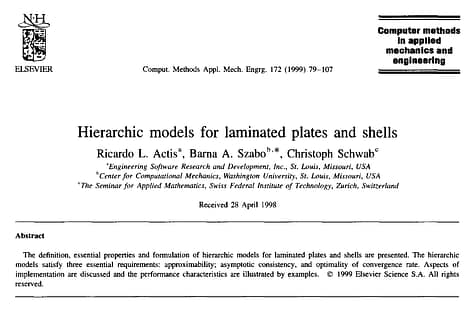
“Hierarchic models for plates and shells” by Drs. Ricardo Actis, Barna Szabó and Christoph Schwab. Comput. Methods Appl. Mech. Engrg. 172 (1999) 79-107.
The concept of Hierarchic Modeling is not new, it was introduced in the 1990s, and together with hierarchic finite element spaces and hierarchic basis functions it was implemented in StressCheck Professional. From the introduction to the 1999 Computer methods in applied mechanics and engineering technical paper “Hierarchic models of laminated plates and shells” by Drs. Actis, Szabó and Schwab:
The notion of hierarchic models differs from the notions of hierarchic finite element spaces and hierarchic basis functions. Hierarchic models provide means for systematic control of modeling errors whereas hierarchic finite element spaces provide means for controlling discretization errors. The basis functions employed to span hierarchic finite element spaces may or may not be hierarchic. Brief explanations follow:
Hierarchic models are a sequence of mathematical models, the exact solutions of which constitute a converging sequence of functions in the norm or norms appropriate for the formulation and the objectives of analysis. Of interest is the exact solution of the highest model, which is the limit of the converging sequence of solutions. In the case of elastic beams, plates and shells the highest model is the fully three-dimensional model of linear elasticity, although even the fully three-dimensional elastic model can be viewed as only the first in a sequence of hierarchic models that account for nonlinear effects, such as geometric, material and contact nonlinearities.
Hierarchic Modeling makes it possible to identify the simplest model that accounts for all features that influence the quantities of interest given the expected accuracy. This is related to the problem-solving principle, known as Occam’s razor, that when presented with competing models to solve a problem, one should select the model with the fewest assumptions, subject to the constraint of required accuracy.
Not all CAE software tools are capable of supporting Hierarchic Modeling in practice, especially for complex applications for which many modeling assumptions are to be examined.
What Do CAE Software Tools Need to Support Hierarchic Modeling?
As previously discussion in our S.A.F.E.R. Simulation blog article on Numerical Simulation, to enable support for a Hierarchic Modeling framework, and by extension the practice of Simulation Governance, CAE software tools must meet three basic requirements:
- The model definition must be independent from the approximation.
- Simple procedures must be available for assessing the influence of modeling assumptions (in support of model validation).
- Simple procedures must be available for objective assessment of the errors of approximation (in support of solution verification).
The above requirements, and how meeting these requirements are supported in practice, are explained in greater detail in our Brief History of FEA page and its narrated video. The first implementation of model hierarchies in a CAE software tool, as explained in the video, was released in 1991 (ESRD’s StressCheck Professional).
An implementation framework meeting these three requirements enables the practice of Simulation Governance, providing the basis for the creation and deployment of engineering Sim Apps. Democratization of Simulation for standardization and automation of new technologies, such as Sim Apps, can be done with proper safeguards provided that the software tools used for the creation and deployment meet these technical requirements.
Why Should Engineers Care About Hierarchic Modeling?
“On the role of hierarchic spaces and models in verification and validation” by Drs. Barna Szabó and Ricardo Actis. Comput. Methods Appl. Mech. Engrg. 198 (2009) 1273-1280.
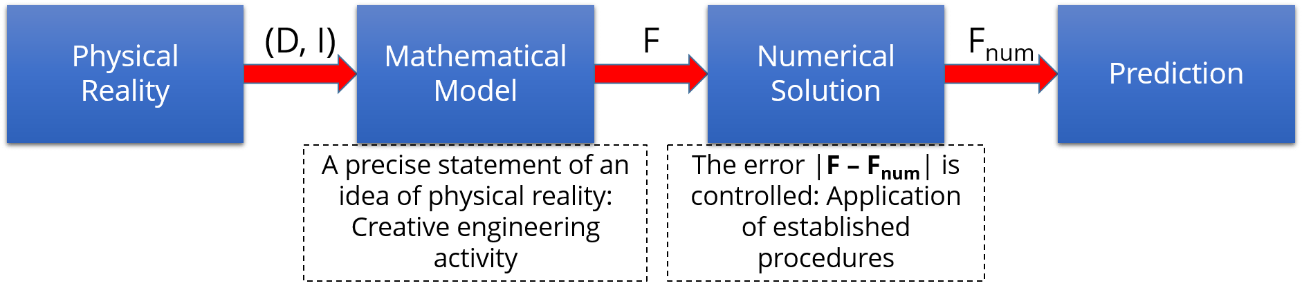
Legacy CAE tools used for Finite Element Modeling were not designed to support Hierarchic Modeling. This is because the concept of Hierarchic Modeling was established many years after the infrastructure of legacy FEA tools was created. Their main limitation is that the model definition and the approximation are not treated separately. Different orders of model complexity cannot be objectively compared by engineering analysts, therefore there is no basis for establishing confidence in the modeling assumptions.
…It is also necessary for the computer implementation
to support hierarchic sequences of models, allowing investigation of the sensitivities of the data of interest and the data measured in validation experiments to the various assumptions incorporated in the model…There is a strong predisposition in the engineering community to view each model class as a separate entity. It is much more useful however to view any mathematical model as a special case of a more comprehensive model, rather than a member of a conventionally defined model class.For example, the usual beam, plate and shell models are special cases of a model based on the three-dimensional linear theory of elasticity, which in turn is a special case of large families of models based on the equations of continuum mechanics that account for a variety of hyperelastic, elastic-plastic and other material laws, large deformation, contact, etc. This is the hierarchic view of mathematical models.
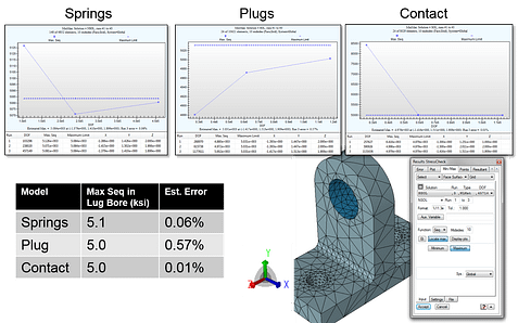
Comparison of maximum von Mises stress convergence for different hierarchic fastened connection models.
To aid finding the simplest model, sensitivity studies via virtual experimentation are recommended. For example, modeling fastened joints may or may not require full multi-body contact effects if the data of interest are sufficiently far from the region of load transfer; bearing load applications, distributed normal springs or partial contact via “plugs” may be sufficient. By extension, if a structural support is to be approximated by distributed springs, the spring coefficients should be defined parametrically so that sensitivity studies are easy to perform.
The following examples and practical applications illustrate how a Hierarchic Modeling framework leads to increased control over and confidence in the engineering decision-making process.
Applications of Hierarchic Modeling In Engineering Practice
We will focus on two practical applications common to many aerospace engineers: fastened (bolted) joint analysis, and the influences of nonlinear effects such as plasticity. Both engineering applications require high-fidelity analyses to represent the data of interest, and are typically sensitive to the modeling assumptions.
Fastened Joint Analysis
ESRD recently provided a webinar titled “Hierarchic Approaches to Modeling Fastened Connections”, which incorporated the main points from the above discussion. The webinar can be viewed below in its entirety.
Through StressCheck Professional‘s Hierarchic Modeling framework, different modeling assumptions are tested for several classes of fastened joints and connections, including lap joints, splice joints and fittings, and in many cases a simpler model was found that represented the data of interest within a sufficient tolerance:
Some of the fastened joint modeling assumptions explored included the following:
- In-plane only vs out-of-plane bending effects on load transfer and detailed stresses
- 2D structural shear connections vs 3D detailed multi-body contact
- 2D bearing loading vs 3D bearing loading vs 3D multi-body contact
- Compression-only normal springs vs multi-body contact
- Fused fasteners vs multi-body contact
- Linear elastic vs. elastic-plastic materials
Without a Hierarchic Modeling framework, exploring these modeling assumptions would be unfeasible in engineering practice, and create a “simulation bottleneck” for engineering analysts.
Linear vs Nonlinear Effects
In some aerospace engineering applications, it may be necessary to investigate the influence of nonlinearities, such as plasticity and/or large deformations, in the results of interest. For that reason a linear solution (i.e. small strain, small deformation and linear elastic material coefficients) must be viewed as the first in a hierarchy of models that includes nonlinear constitutive relations, finite deformation and mechanical contact.
In a Hierarchic Modeling framework, engineering analysts should not need to change the discretization (i.e. mesh, element types and mapping) when transitioning from a linear to nonlinear model analysis for example; the switch should be seamless and simple, allowing the order of the model to increase on demand.
The following demo videos examine two case studies in nonlinear effects, in which the Hierarchic Modeling framework of StressCheck Professional was used to assess the influence of simplifying modeling assumptions without changing the discretization.
Geometric Nonlinearities
In the first case study, a linear vs. geometric nonlinear (large strain/large displacement) analysis for a 3D helical spring was performed:
Performing a geometric nonlinear analysis for the helical spring, in which equilibrium is satisfied in the deformed configuration, required no interaction with the model inputs or discretization parameters. The engineering analyst simply starts from a converged linear solution as the first step in the geometric nonlinear iterations.
The model hierarchies were then compared in live results processing with minimal effort, allowing the engineering analyst to quickly assess how accounting for large displacements/rotations affects the outcome of the results.
Material Nonlinearities
In the second case study, elastic-plastic materials are assigned to a detailed 3D eyebolt geometry, allowing plasticity to develop as the eyebolt is overloaded in tension:
To incorporate plasticity into the model, it was only required to update the material properties from linear to elastic-plastic; no other change in model inputs was required. Then, after a converged linear solution was available, a material nonlinear analysis was seamlessly initiated.
As in the previous case study, both models were available for assessment in live results processing, allowing the engineering analyst to determine whether material nonlinear effects are significant at the given load level (i.e. is the plasticity extensive) or the plastic zone is fully confined by elastic material.
Summary
As demonstrated in the above examples, and articulated in the technical paper excerpts, support for a seamless transition between model orders and theories is made possible by the implementation of a Hierarchic Modeling framework. To implement Hierarchic Modeling, CAE software tools must also allow separation of model definition from the discretization (in legacy FEA software, the definition of the model and the numerical approximation are combined, necessitating large element libraries). Without this clear separation, it is not feasible to reliably perform verification and validation in engineering practice.
Additionally, engineering analysts should expect modern FEA and CAE tools to support “what if” and sensitivity studies, such that modeling assumptions can be easily assessed and the simplest model used with confidence. As more and more engineering organizations look to democratize simulation, and virtual experimentation is increasingly used, it is essential to have numerical simulation tools that treat model definition separately from the approximation.
Finally, through the use of hierarchic finite element spaces and mathematical models it is possible to control approximation errors separately from modeling errors, while providing objective measures of solution quality for every result, anywhere in the model, in support of the increasing simulation demands on engineers.
How We Can Help…


Leave a Reply
We appreciate your feedback!
You must be logged in to post a comment.