
By Dr. Barna Szabó
Engineering Software Research and Development, Inc.
St. Louis, Missouri USA
In the engineering sciences, mathematical models are used as sources of information for making technical decisions. Consequently, decision-makers need convincing evidence that relying on predictions from a mathematical model is justified. Such reliance is warranted only if:
- the model has been validated, and its domain of calibration is clearly defined;
- the errors of approximation are known to be within permissible tolerances [1].
Model development projects are essentially scientific research projects. As such, they are subject to the operation of the Kuhn Cycle, named after Thomas Kuhn, who identified five stages in scientific research projects [2]:
- Normal Science – Development of mathematical models based on the best scientific understanding of the subject matter.
- Model Drift – Limitations of the model are encountered. Certain quantities of interest cannot be predicted by the model with sufficient reliability.
- Model Crisis – Model drift becomes excessive. Attempts to remove the limitations of the model are unsuccessful.
- Model Revolution – This begins when candidates for a new model are proposed. The domain of calibration of the new model is sufficiently large to resolve most if not all, issues identified with the preceding model.
- Paradigm Change – A paradigm consists of the fundamental ideas, methods, language, and theories that are accepted by the members of a scientific or professional community. In this phase, a new paradigm emerges, which then becomes the new Normal Science.
The Kuhn cycle is a valuable concept for understanding how mathematical models evolve. It highlights the importance of paradigms in shaping model development and the role of paradigm shifts in the process.
Example: Linear Elastic Fracture Mechanics
In linear elastic fracture mechanics (LEFM), the goal is to predict the size of a crack, given a geometrical description, an initial crack configuration, material properties, and a load spectrum. The mathematical model comprises (a) the equations of the theory of elasticity, (b) a predictor that establishes a relationship between a functional defined on the elastic stress field (usually the stress intensity factor), and increments in crack length caused by the application of constant amplitude cyclic loads, (c) a statistical model that accounts for the natural dispersion of crack lengths, and (d) an algorithm that accounts for the effects of tensile and compressive overload events.
Evolution of LEFM
The period of normal science in LEFM began around 1920 and ended in the 1970s. Many important contributions were made in that period. For a historical overview and commentaries, see reference [3]. Here, I mention only three seminal contributions: The work of Alan A. Griffith, who investigated brittle fracturing, George. R. Irwin modified Griffith’s theory for the fracturing of metals, and Paul C. Paris proposed the following relationship between the increment in crack length per cycle of loading and the stress intensity factor K:
{da\over dN} = C(K_{max}-K_{min})^mwhere N is the cycle count, C and m are constants determined by calibration. This empirical formula is known as Paris’ law. Numerous variants have been proposed to account for cycle ratios and limiting conditions.
In 1972, the US Air Force adopted damage-tolerant design as part of the Airplane Structural Integrity Program (ASIP) [MIL-STD-1530, 1972]. Damage-tolerant design requires showing that a specified maximum initial damage would not produce a crack large enough to endanger flight safety. The paradigm that Paris’ law is the predictor of crack growth under cyclic loading is now universally accepted.
Fly in the Ointment
Paris’ law is defined on two-dimensional stress fields. However, it is not possible to calibrate any predictor in two dimensions. The specimens used in calibration experiments are typically plate-like objects. In the neighborhood of the points where the crack front intersects the surfaces, the stress field is very different from what is assumed in Paris’ law. Therefore, the parameters C and m in equation (1) are not purely material properties but also depend on the thickness of the test specimen. Nevertheless, as long as Paris’ law is applied to long cracks in plates, the predictions are accurate enough to be useful for practical purposes. However, problems arise when a crack is small relative to the thickness of the plate, for instance, a small corner crack at a fastener hole, which is one of the very important cases in damage-tolerant design. Attempts to fix this problem through the introduction of correction factors have not been successful. First, model drift and then model crisis set in.
The consensus that the stress intensity factor drives crack propagation consolidated into a dogma about 50 years ago. New generations of engineers have been indoctrinated with this belief, and today, any challenge to this belief is met with utmost skepticism and even hostility. An unfortunate consequence of this is that healthy model development stalled about 50 years ago. The key requirement of damage-tolerant design, which is to reliably predict the size of a crack after the application of a load spectrum, is not met even in those cases where Paris’ law is applicable. This point is illustrated in the following section.
Evidence of the Model Crisis
A round-robin exercise was conducted in 2022. The problem statement was as follows: A centrally cracked 7075-T651 aluminum panel of thickness 0.245 inches, width 3.954 inches, a load spectrum, and the initial half crack length (denoted by ) of 0.070 inches. The quantity of interest was the half-crack length as a function of the number of cycles of loading. The specimen configuration and notation are shown in Fig. 1(a). The load spectrum was characterized by two load maxima given in terms of the nominal stress values σ1 = 22.5 ksi, σ2 = 2σ1/3. The load σ = σ1 was applied in cycles numbered 1, 101, 201, etc. The load σ = σ2 was applied in every other cycle. The minimum load was zero for all cycles. In comparison with typical design load spectra, this is a highly simplified spectrum. The participants in this round-robin were professional organizations that routinely provide estimates of this kind in support of design and certification decisions.
Calibration data were provided in the form of tabular records of da/dN corresponding to (Kmax – Kmin) for various (Kmin/Kmax) ratios. The participants were asked to account for the effects of the periodic overload events on the crack length.
A positive overload causes a larger increment of the crack length in accordance with Paris’ law, and it also causes compressive residual stress to develop ahead of the crack tip. This residual stress retards crack growth in subsequent cycles while the crack traverses the zone of compressive residual stress. Various models have been formulated to account for retardation (see, for example, AFGROW – DTD Handbook Section 5.2.1.2). Each participant chose a different model. No information was given on whether or how those models were validated. The results of the experiments were revealed only after the predictions were made.
Fig. 1 (b) shows the results of the experiments and four of the predicted outcomes. In three of the four cases, the predicted number of cycles is substantially greater than the load cycles in the experiments, and there is a large spread between the predictions.
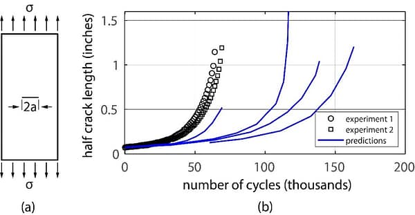
Figure 1: (a) Test article. (b) The results of experiments and predicted crack lengths.
This problem is within the domain of calibration of Paris’ law, and the available calibration records cover the interval of the (Kmax – Kmin) values used in the round robin exercise. Therefore, in this instance, the suitability of the stress intensity factor to serve as a predictor of crack propagation is not in question.
Noting that the primary objective of LEFM is to provide estimates of crack length following the application of a load spectrum, and this is a highly simplified problem, these results suggest that retardation models based on LEFM are in a state of crisis. This crisis can be resolved through the application of the principles and procedures of verification, validation, and uncertainty quantification (VVUQ) in a model development project conducted in accordance with the procedures described in [1].
Outlook
Damage-tolerant design necessitates reliable prediction of crack size, given an initial flaw and a load spectrum. However, the outcome of the round-robin exercise indicates that this key requirement is not currently met. While I’m not in a position to estimate the economic costs of this, it’s safe to say they must be a significant part of military aircraft sustainment programs.
I believe that to advance LEFM beyond the crisis stage, organizations that rely on damage-tolerant design procedures must mandate the application of verification, validation, and uncertainty quantification procedures, as outlined in reference [1]. This will not be an easy task, however. A paradigm shift can be a controversial and messy process. As W. Edwards Deming, American engineer, economist, and composer, observed: “Two basic rules of life are: 1) Change is inevitable. 2) Everybody resists change.”
References
[1] Szabó, B. and Actis, R. The demarcation problem in the applied sciences. Computers and Mathematics with Applications. 162 pp. 206–214, 2024.
[2] Kuhn, T. S., The structure of scientific revolutions. Vol. 962. University of Chicago Press, 1997.
[3] Rossmanith, H. P., Ed., Fracture Mechanics Research in Retrospect. An Anniversary Volume in Honour of George R. Irwin’s 90th Birthday, Rotterdam: A. A. Balkema, 1997.
Related Blogs:
- Where Do You Get the Courage to Sign the Blueprint?
- A Memo from the 5th Century BC
- Obstacles to Progress
- Why Finite Element Modeling is Not Numerical Simulation?
- XAI Will Force Clear Thinking About the Nature of Mathematical Models
- The Story of the P-version in a Nutshell
- Why Worry About Singularities?
- Questions About Singularities
- A Low-Hanging Fruit: Smart Engineering Simulation Applications
- The Demarcation Problem in the Engineering Sciences
- Model Development in the Engineering Sciences
- Certification by Analysis (CbA) – Are We There Yet?
- Not All Models Are Wrong
- Digital Twins
- Digital Transformation
- Simulation Governance
- Variational Crimes


Leave a Reply
We appreciate your feedback!
You must be logged in to post a comment.