

SAINT LOUIS, MISSOURI – November 7, 2017
Relentless Business Drivers in the Aerospace & Defense Industry
The global aviation, aerospace, and defense industries face unrelenting pressure for ever-increasing levels of operational performance, lifecycle reliability, and mission robustness in their products, platforms, and programs delivered to commercial and military customers. This is occurring concurrently with greater demand for overall system performance that is faster, lighter, quieter, smarter, greener, and more connected. And of course, customers want all of this and more at less cost to procure, reduced time to deploy, and cheaper to maintain!
These business drivers have unleashed a level of interconnected complexity across nearly every organizational function, R&D process, and product line of the modern A&D enterprise. A new norm of debilitating complexity permeates today’s aerospace business throughout program management, requirements planning, system design, engineering analysis, manufacturing workflows, product line variants, supply chain collaboration, and in-service sustainment. While dozens of promising new technologies, software tools and enterprise solutions have emerged in recent years to advance these organizational functions, they have unfortunately added yet more layers of technical complexity along nearly every axis.

The U.S. Navy’s aircraft fleet requires high-fidelity structural analysis for design and to keep airborne over a longer lifecycle
A&D Program Pains and Engineering Stresses
While many OEM prime contractors and their supply chain partners have risen to meet the challenge of greater performance and higher complexity, others have struggled as evidenced by the number of major programs which encounter substantial overruns in budget or schedule, or both. Not that long ago the U.S. GAO reported that major defense programs experienced an average schedule delay approaching two years, with an average budget overrun of more than 25%.
As this trend is unsustainable, program managers are under substantial pressure to revisit obsolete assumptions and defend legacy thinking that impacts the technology maturity curve. One such example is the expectation that years of investment in the automation, standardization, and integration of tools for CAD, CAE, CAM, PDM, Visualization, and DMfg now make high concurrency of final design, tooling, testing, and manufacture of production aircraft less risky.
The inconvenient truth is that simultaneous advancements across numerous technology silos often injected more complexity and time than expected, and in doing so created new systemic risks especially after they were connected and integrated. As a consequence, there was often less, not more, time left in the schedule for final prototyping, optimization, supply chain collaboration, and flight testing. The pains of a new program often became the new stresses on engineering.
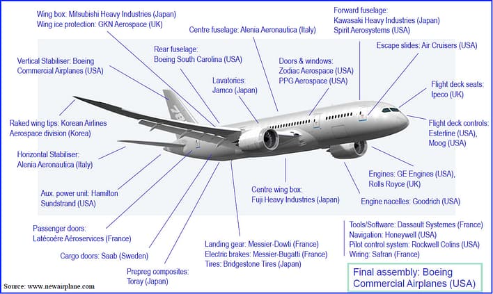
The high performance of the Boeing 787 Dreamliner is made possible by a complex interdependent global network of partners and suppliers with design engineering contributions, not just manufacturing.
Diminishing Returns from Investing in More of the Same Technology

Faced with an avalanche of complexity, many legacy technologies – along with the organizational competencies, workflows, and tools built upon them – have become non-linear to further investments for improving. That is, an incremental improvement in one function does not always translate into immediate or scalable improvements across the entire product development ecosystem. Some highly-touted advancements often introduce more uncertainty and complexity than the interdependent web of new product development can quickly absorb. Aerospace managers have come to realize that a seductive innovation in one domain may cascade into a series of downstream hurdles that are not always fully understood at the onset of the new technology adoption maturity curve.
In response to schedule-eating, budget-busting complexity, engineering groups are seeking new methods and tools that aren’t limited to more of the same advancements to their organization’s competency and capacity to meet higher product performance requirements. They now demand that new investments also begin to distill out complexity and wring out risk which has become increasingly tricky to define and unwieldy to manage. Particularly attractive are new methodologies and technologies that are conceptually so simple, reliable, and robust that they may be used with confidence by engineering specialists as well as non-experts alike.
Simulation technologies and analysis software used in the structures, stress, strength, DaDT, materials, and manufacturing support groups are particularly ripe for simplification and “robustification”. Only then can the promise of the democratization of simulation to compress product development cycles through simulation-driven design finally be achieved, without adding yet more complexity and risk.
The State of Simulation and Modeling in Aerospace Engineering Groups
Over a period of four decades, application software developed for performing simulation based on the finite element method (FEM) has matured to deliver an ever-expanding list of functionality and features across a steadily widening computational spectrum of multiple physics. As finite element analysis (FEA) software products became more capable and feature-rich, they also became more complex to learn, time consuming to master, prickly to operate, and problematic to trust. FEA is justifiably referred to as an “art form” for expert analysts due to all the sources of assumptions, approximations, idealizations, discretizations, judgements, and errors an engineer must deal with to arrive at a “good” solution which they can defend in a design review.
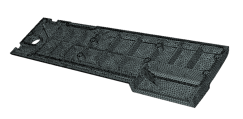
What element type(s) and size(s) are best for performing detail stress analysis using legacy FEA codes – only the experts know!
The evidence speaks for itself that when different users attempt to solve the same computational mechanics problem by using different FEA software – or employing the same code but with subjectively different models, meshes, and element types used – it is not unusual to generate very different analytical results. It is no secret to the experts and their managers that most of the effort and time of FEA is spent in the laborious pre-processing steps of creating bad models to finally arrive at good ones, instead of in the post-processing stage leveraging the results to optimize design performance. Simulation analysts with deep FEA expertise rightfully take pride in their profession for mastering all the nuances and minutia which can influence the quality of their work.
As a consequence, some aerospace engineering managers think of FEA as definitely the best analysis tool for the highest quality results, but only after all other analysis methods have been exhausted! The use of engineering handbooks, design curves, empirical data, closed form solutions, previous designs, and elaborate spreadsheets to calculate and pencil-whip margins of safety is seen as preferable to spending more time building, running, debugging, and tuning finite element models. This is not to discount the power and accuracy of finite element-based stress analysis – especially when compared to the alternative of more physical testing – but just an honest assessment that there is a very significant cost to obtain the higher-fidelity solutions that FEA offers.
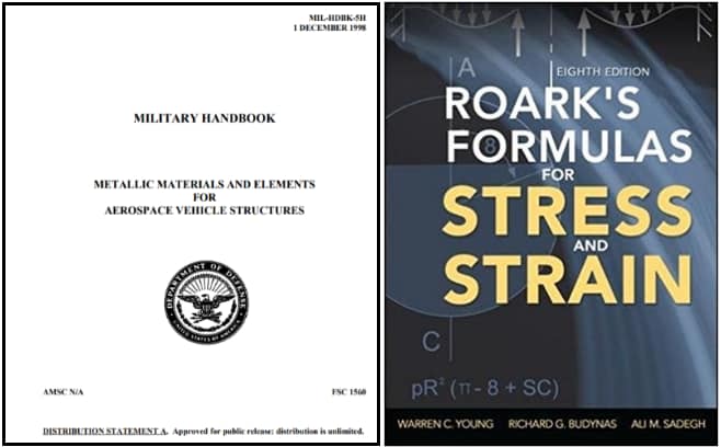
Engineering handbooks like he MIL-HDBK-5H and Roark’s Formulas for Stress and Stress are frequently extended well outside of their ranges, resulting in more errors and unknowns
Coming Up Next…
In Part 2 of this S.A.F.E.R. Simulation series we will examine the increasing demands on the structures engineering simulation function and the often misunderstood challenges they experience when using legacy analysis technologies based on the finite element method. The origins and differences between finite element modeling and predictive computational numerical simulation will be summarized. The capabilities of ESRD’s numerical simulation technology base, and software products build upon it including StressCheck™ and Smart Sim Apps in a Digital CAE Handbook, will be overviewed. In Part 3 we will profile use-case examples from A&D that substantiate the benefits to engineers and value to their programs from the use of a newer generation of smarter simulation software that is Simple, Accurate, Fast, Efficient, and Reliable – S.A.F.E.R – for both the frequent expert and occasional non-expert user alike.


Leave a Reply
We appreciate your feedback!
You must be logged in to post a comment.