Tip: Start typing in the input box for immediate search results.Can't find what you're looking for? Submit a support request here.
Dynamic Display Operations Overview
Introduction
All dynamic display operations can be performed by dragging the mouse across the Model View display area with the right mouse button depressed. This technique is used for rotation (default), translation, dynamic zoom and box zoom. Hot keys, as well as the icons in the Views Toolbar, may be used to switch between dynamic display operations.
Additionally, function keys are available to perform the above dynamic display operations via the keyboard and an interactive Navigation Cube, located in the bottom left of the Model View, may be left-clicked at its vertices, edges or faces to access standard model view orientations.
Mouse Usage
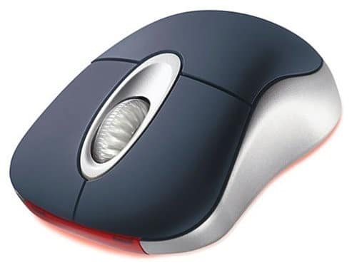
Standard 3-Button Mouse

For a standard 3-button mouse, the following default behavior may be observed when the mouse cursor is hovering over the Model View display area:
- Clicking the left mouse button: the command specified by the C/A/O/M configuration is initiated.
- Hold left mouse button + drag when Action is set to Select: marquee selection of one or more objects.
- Clicking and releasing the right mouse button: abort multi-step operation/cancel object selection.
- Clicking and holding the right mouse button: display Context Menu options for the cursor location.
- Hold right mouse button + drag: the model is rotated.
- Hold mouse wheel down + drag: the model is translated.
- Scroll mouse wheel up/down: the model is zoomed in/out, respectively.
The right mouse button may also be used to select a point or node as the center of rotation when the “Center Rotation” icon is enabled (see Views Toolbar Overview).
Navigation Cube
Left-clicking on a vertex, edge, or face of the Navigation Cube—located in the bottom-left corner of the Model View—allows the user to interactively set the model orientation to a standard view (e.g., Front, Back, Isometric, etc.). A blue preselection highlight will appear on the cube at the mouse cursor location to indicate the expected change in model orientation.

Clicking the same vertex, edge, or face repeatedly will rotate the view:
- 120 degrees clockwise for vertices
- 90 degrees clockwise for edges or faces
The Navigation Cube can be shown or hidden by toggling the Navigation Cube icon.
Note: The triad or the combined triad/navigation cube display can be hidden by right-clicking on it and selecting Hide Triad Axis from the context menu. It can be restored using the main context menu via Unhide > Triad Axis.
The following demonstrates how to interact with the Navigation Cube feature:
Dynamic Display Hot Keys
When the Model View display area has focus, StressCheck employs convenient hotkeys to center the model, display the previous model view, and change the right mouse button behavior. These hotkeys are also available in icon form in the Views Toolbar and under “Move” in the Display Menu Overview.
- To center the model, press “C” on the keyboard.
- To display the previous model view, press “A” on the keyboard.
- Setting right mouse button + drag behavior:
- Translate, press “T” on the keyboard.
- Zoom, press “Z” on the keyboard.
- Box zoom, press “B” on the keyboard.
- Rotate, press “R” on the keyboard.
When box zoom is set as the right mouse button behavior, you may draw a rectangle around the area of interest by holding down the right mouse button and setting the zoom region. When the right mouse button is released, this area will be expanded to fill the Model View display area.
3Dconnexion SpaceMouse

StressCheck supports 3Dconnexion SpaceMouse products for dynamic display operations. If a 3Dconnexion product and standard 3-button mouse are both installed, the user may employ the 3Dconnexion product to dynamically manipulate the model while the standard 3-button mouse is ready to execute the C/A/O/M configuration command.
Drivers can be downloaded from www.3dconnexion.com.
Keyboard Usage
Function Keys
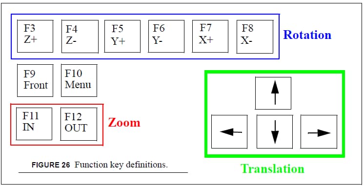
The dynamic display operation function keys on your keyboard are defined as shown in Figure 1:

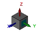
The function keys are active only when the display window has focus. The rotation keys are for the angular rotation about the global coordinate axis. The rotation step after each click can be adjusted in the Camera/Lighting dialog. The default step size is 10 degrees. Translation and zoom are self-explanatory.
 Serving the Numerical Simulation community since 1989
