
By Dr. Barna Szabó
Engineering Software Research and Development, Inc.
St. Louis, Missouri USA
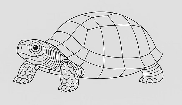
The architecture of legacy finite element codes evolved much like the turtle. While the carapace initially provided a protective advantage, it ultimately hindered mobility and respiratory efficiency. Because the shell is fused to the spine and ribs, a turtle cannot expand its chest as other reptiles do.
Evolution—whether biological or digital—builds upon existing structures in ways that can produce design flaws, or even evolutionary dead ends. Legacy finite element codes have entered such an evolutionary cul-de-sac. The very structures that allowed these codes to survive the resource-scarce 1960s now impose comparable constraints on adaptability, rendering them inadequate for the emerging technical demands of integrating numerical simulation with explainable AI. To understand how this situation developed, a brief historical survey is needed.
Historical Notes
There was a surge of interest in matrix methods applied to problems of elasticity and, more generally, continuum mechanics in the 1960s and ’70s. A center of activity was a series of three international conferences held at the Wright-Patterson Air Force Base in Dayton, Ohio. The first Conference (26–28 October 1965) addressed plate/shell elements, stiffness matrices, convergence, and large-scale structural applications. The conference proceedings [1] represent a fair survey of the knowledge base existing at that time. NASA issued a request for proposals in the same year for the development of a general-purpose finite element structural analysis program, which later became NASTRAN and served as a prototype for other legacy finite element codes in use today.
The early development of the finite element method proceeded under two severe constraints. One was a lack of understanding of its theoretical foundations. As reference [1] attests, the work relied largely on an intuitive, trial‑and‑error approach—“see whether it works”—of the kind engineers use when confronted with a new problem. The Wright Brothers’ story is a famous example of this.
The second constraint was the limitation of computational resources. For example, solving a 200×200 dense eigenvalue problem required out‑of‑core methods or reduced‑basis approaches, even on the best computers then available, such as the CDC 6600 or the IBM 7094.
These constraints placed strict limits on the types of elements, the number of nodes, and the kinds of mappings that could be used. By the time these limitations were lifted, finite element codes had already become firmly embedded in engineering practice, and any substantive change would have required major revisions. As a result, constraints that no longer exist continue to handicap legacy finite element codes to this day.
Development Along Two Distinct Lines: Art and Science
The term cladogenesis (branching) is used by biologists to describe the splitting of an evolutionary lineage. A similar splitting occurred in the evolution of the finite element method.
Starting in the early 1970s, mathematicians began to investigate the theoretical foundations of the finite element method. Their work centered on the use of function spaces constructed from piecewise-polynomial functions defined on a finite element mesh to approximate the solutions to partial differential equations in a prescribed norm, typically the energy norm [2]. Fundamental questions such as stability, convergence rates, optimal discretization choices, and a posteriori error estimation were systematically addressed. By the mid‑1980s, this line of inquiry had produced a substantial body of rigorous results, establishing finite element analysis as a bona fide branch of applied mathematics.
Owing to evolutionary constraints and the absence of a shared conceptual framework and vocabulary, the developers of legacy finite element codes largely ignored these advances. They continued to update their solvers and user interfaces, but left the underlying element formulations—and the many technical limitations tied to them—largely untouched. Thus it came to pass that the finite element method effectively split into two distinct branches: the art of finite element modeling and the science of finite element analysis.
The term finite element modeling refers to the engineering practice of constructing a numerical problem by assembling elements from a finite element library to approximate the load–displacement response of a complex structure, such as in automobile crash dynamics simulations and in the load modeling of an airframe. The numerical problem stands on its own; it is not understood as an approximation to a mathematical problem. In contrast, the term finite element analysis refers to the process of approximating the solution of a well-posed mathematical problem.
Finite element modeling, when properly understood and applied, is an important and highly effective engineering tool. Serious problems arise, however, when it is used for situations that require an application of the science of finite element analysis. Unfortunately, this is a common occurrence.
The Current Objectives of Model Development
As advances in theory and computing have removed many of the constraints that once shaped engineering practice, the goals of model development today differ markedly from those of the pre‑computer era. The evolution of plate and shell models provides a clear example of how these objectives have shifted over time. To show how model development has been driven by changing scientific knowledge, computational capabilities, and now artificial intelligence, I will trace the progression of plate and shell models across three periods.
The Classical Period (Late 1890s to the 1960s)
In formulating classical plate and shell models, the goal was to find an approximation to the solution of a fully three-dimensional theory of elasticity problem on domains of small thickness. Dimensional reduction was used for this purpose; that is, the problem was recast such that the 3D problem of elasticity could be solved on two-dimensional domains—typically the mid-surface of a plate or shell. To achieve this, four types of assumptions were introduced:
a) assumptions regarding the mode of deformation (e.g., neglecting shear deformation),
b) assumptions about constitutive relationships
c) assumptions concerning idealization of loading
d) assumptions concerning idealization of kinematic boundary conditions.
It was proven in 1959 that the stresses and strains obtained from a solution of Kirchhoff’s plate theory converge in a mean‑square sense to a solution in elasticity theory as the plate thickness approaches zero [3]. This was the first rigorous justification of the Kirchhoff model as the correct asymptotic limit of 3D elasticity for vanishing thickness. Similar results were reported for Reissner-Mindlin plates in [4]. For a finite thickness, these assumptions introduce errors that are built into the formulation itself, called model-form errors.
Element-Centric Development: The Pre-Science Period (1960s and 70s)
According to Thomas Kuhn, a pre‑science period is marked by the absence of a common conceptual framework—no shared assumptions, no standard methods, and no consensus about what constitutes a valid model or solution [5]. Instead, development proceeds largely by trial‑and‑error rather than by coherent scientific guidance. That prevailed in the engineering research on the finite element method, as reflected in the proceedings of the three international conferences held at Wright–Patterson Air Force Base in the 1960s and 70s mentioned earlier.
The focus of the investigation was element-centric, with the goal of defining finite elements that had the approximate stiffness of the corresponding segment of the plate or shell being modeled. The criterion for acceptance was whether the element passed certain benchmark tests for which the exact solution was known. The underlying argument was that, because the element worked in these particular cases, it could be expected to work in all cases—an obvious logical fallacy. These elements survive in the libraries of legacy finite element codes to the present day.
Model-Centric Development: Integration with Explainable AI (XAI)
Given our computational power today, we are free to model plates and shells as fully three-dimensional objects and to control model form not only by relaxing restrictive assumptions about deformation modes but also by removing the assumption of linear material behavior. Our goal in model development has shifted from using simplifying assumptions to make the problem tractable by classical methods to controlling model‑form errors. In other words, the original reasons for creating classical plate and shell models no longer exist.
The Basic Requirements of AI Integration
The requirements that define explainable AI are stated in a 2021 NIST report [6] as follows:
- Explanation — The system provides accompanying evidence, support, or reasoning for its outputs and/or processes (not just the result, but why it reached that conclusion).
- Understandable — Explanations must be tailored and comprehensible to the individual user.
- Explanation accuracy — The provided explanation must correctly and faithfully reflect the process the system used to generate the output.
- Knowledge limits — The system only operates within the conditions for which it was designed, and it communicates its own limitations (e.g., refuses to predict when data or parameters lie outside of the domain of calibration).
Integrating numerical simulation with XAI imposes several requirements on the formulation, calibration, validation, and operation of mathematical models—none of which are supported by legacy finite element codes. The main requirements are the separate control of model form and discretization errors, and the definition of the calibration domain, which is a recently introduced concept [7].
A Comment on Recent Acquisitions
In view of the evolutionary history of the finite element method, I was surprised to learn of three major acquisitions: Synopsys/Ansys (2025), Siemens/Altair (2025), and Cadence/Hexagon (2026). The corporate announcements explaining these moves envision merging electronic design automation (EDA) with “Multiphysics simulation” to create a “seamless silicon-to-systems pipeline”.
In acquisitions of this magnitude, one assumes an army of lawyers and accountants performed exhaustive due diligence, tying down every financial and legal loose end. However, the acquiring organizations appear not to have applied similar diligence to the underlying technology. Had they done so, they would have discovered that the core technology is more than 40 years out of date. Moreover, because these legacy architectures cannot provide the rigorous, independent error control required for Explainable AI, they lack the foundational capabilities necessary to meet the objectives cited for their acquisition.
For evolutionary reasons, that turtle wont hunt.
Outlook
Realizing the promise of explainable AI in engineering requires a fundamental shift to science-based numerical simulation technology. The good news is that the technological foundations for integrating numerical simulation with AI already exist and have been advancing for decades. To remove the primary barriers to understanding this body of work, I have outlined a conceptual framework in a series of short technical notes, presented as accessible blog posts. I recently published a collection of these notes [8] to serve as a roadmap for this transition.
References
[1] Proceedings: Matrix Methods in Structural Mechanics. J. S. Przemieniecki et al. (Editors), AFFDL-TR-66-80, November 1966. Defense Technical Information Center (DTIC) accession number AD-646300. [2] Babuška I. and Aziz, A. K. Lectures on Mathematical Foundations of the Finite Element Method. University of Maryland, College Park, 1972. [3] Morgenstern, D. Herleitung der Plattentheorie aus der dreidimensionalen Elastizitätstheorie. (Derivation of plate theory from three-dimensional elasticity theory.) Archive for Rational Mechanics and Analysis. 4(1), pp.145-152, 1959. [4] Braess, D., Sauter, S., and Schwab, C. On the justification of plate models. Journal of Elasticity. 103(1), pp. 53-71, 2011. [5] Kuhn, T. S. The structure of scientific revolutions. University of Chicago Press, 1997. [6] Phillips, P., Hahn, C., Fontana, P., Yates, A., Greene, K., Broniatowski, D. and Przybocki, M. Four Principles of Explainable Artificial Intelligence. Interagency/Internal Report NISTIR 8312. Gaithersburg, MD, 2021. [7] Szabó, B. and Actis, R. The demarcation problem in the applied sciences. Computers & Mathematics with Applications, 162, pp. 206-214, 2024. [8] Szabó. B. Bridging the Gap: Advancing Finite Element Analysis in Numerical Simulation. PaperTrue Ltd., 2025.Related Blog Posts:
- A Memo from the 5th Century BC
- Obstacles to Progress
- Why Finite Element Modeling is Not Numerical Simulation?
- XAI Will Force Clear Thinking About the Nature of Mathematical Models
- The Story of the P-version in a Nutshell
- Why Worry About Singularities?
- Questions About Singularities
- A Low-Hanging Fruit: Smart Engineering Simulation Applications
- The Demarcation Problem in the Engineering Sciences
- Model Development in the Engineering Sciences
- Certification by Analysis (CbA) – Are We There Yet?
- Not All Models Are Wrong
- Digital Twins
- Digital Transformation
- Simulation Governance
- Variational Crimes
- The Kuhn Cycle in the Engineering Sciences
- Finite Element Libraries: Mixing the “What” with the “How”
- A Critique of the World Wide Failure Exercise
- Meshless Methods
- Isogeometric Analysis (IGA)
- Chaos in the Brickyard Revisited
- Why Is Solution Verification Necessary?
- Variational Crimes and Refloating the Costa Concordia
- Lessons From a Failed Model Development Project
- Where Do You Get the Courage to Sign the Blueprint?
- Great Expectations: Agentic AI in Mechanical Engineering
- The Differences Between Calibration and Tuning
- Honored in the Breach
- Remembering Ivo Babuška


Leave a Reply
We appreciate your feedback!
You must be logged in to post a comment.