 Serving the Numerical Simulation community since 1989


By Dr. Barna Szabó
Engineering Software Research and Development, Inc.
St. Louis, Missouri USA
Reliable strength prediction in laminated composites requires the simultaneous control of discretization and model-form errors. Conventional plate and shell formulations cannot generally provide this control. The hp-version of the finite element method offers a practical solution.
In a nutshell, the name hp-version reflects the fact that the quality of a finite element solution depends on both the mesh and the polynomial degrees assigned to the elements. The letters h and p denote the size of the largest element in the mesh and the smallest polynomial degree assigned to the elements, respectively. For a broad class of problems, including elasticity, properly designed hp discretizations can achieve exponential rates of convergence [1].
The hp-version is particularly well suited for the analysis of laminated composites because it accommodates large element aspect ratios without locking, achieves high computational efficiency, and enables simultaneous control of model-form and discretization errors in composite plate and shell analyses. These capabilities are essential prerequisites for the evaluation and ranking of alternative failure theories.
Model-form errors arise from simplifying assumptions embedded in a mathematical model. Conventional plate and shell formulations incorporate assumptions concerning the through-thickness displacement field (e.g., first-order, higher-order, zig-zag, and layer-wise theories), material behavior, and boundary conditions [2,3]. These assumptions introduce model-form errors whose magnitude is generally unknown.
In contrast, the hp-version supports thin solid elements, allowing independent control of discretization and model-form errors. Thin solid elements are mapped hexahedra in which one dimension is much smaller than the other two. Converging sequences of numerical solutions are obtained using the anisotropic finite element spaces S(Δ,p,p,q). Here, Δ represents the mesh, while p and q represent the polynomial degrees of the displacement components in the in-plane and transverse directions, respectively.
In the in-plane or mid-surface directions, the finite element mesh and the polynomial degree p assigned to the elements govern discretization errors. Within the adopted three-dimensional elasticity model, increasing q reduces errors associated with the through-thickness representation of the displacement and stress fields. Consequently, the analyst can explicitly control convergence, systematically reduce model-form errors, and focus computational effort where additional resolution is needed.
The exact solutions of solid mechanics problems are typically piecewise analytic. Over large interior regions of many plate and shell structures, the solution is typically analytic, leading to exponential p-convergence and permitting the efficient use of elements with large aspect ratios. Consequently, layerwise representations of laminated composites can often be employed economically. Near edges, corners, interfaces, and other locations exhibiting boundary-layer behavior, however, stresses may vary rapidly over short distances. In such regions, local mesh refinement and higher q values are often required to achieve the desired level of accuracy [4].
The hp-version resolves severe interlaminar stress gradients and thin-scale features without suffering from locking. In contrast, traditional h-version approaches often require excessively fine, nearly isotropic meshes, resulting in substantially higher computational cost.
Formulation of Predictors for the Onset of Failure
An elasticity problem formulated for a plate or shell structure made of laminated composites is typically based on a set of idealizations involving a sequence of homogeneous orthotropic laminae characterized by effective elastic material properties. This homogenization implies idealized fiber arrangements within the laminae. It is further assumed that the laminae are perfectly bonded at their interfaces. In reality, however, the fiber architecture differs significantly from this idealized picture. Fibers are irregularly distributed, may exhibit waviness or kinks, and the interfaces between adjacent layers are not sharply defined.
One may question the value of obtaining an accurate solution to an idealized elasticity problem when the underlying assumptions differ substantially from reality. The answer is that such a solution serves as the reference against which failure-initiation criteria are developed and calibrated. Therefore, consistency requires that the same reference be used when those criteria are subsequently applied.
Two important caveats should be kept in mind:
- The material parameters used in failure theories are typically determined from coupon tests designed to produce a well-defined and nearly uniform stress state within the gauge section of the specimen. By contrast, the stress field computed from an idealized elasticity model may be highly non-uniform and may even contain stress singularities. Consequently, pointwise stresses determined from the three-dimensional elasticity solution are generally not good predictors of failure initiation.
- Pointwise stresses, as defined in continuum mechanics, are mathematical idealizations. Real materials have microstructure, so physically meaningful stress measures must be associated with quantities averaged over a volume at least as large as a representative volume element (RVE).
- An RVE is a volume over which appropriately averaged microscopic fields and energy densities reproduce the corresponding macroscopic continuum quantities, so that the effective material properties become insensitive to the particular boundary conditions imposed on the volume.
- Experimentally determined material parameters are random variables; therefore, failure prediction is inherently stochastic.
Formulating predictors is an open-ended problem; numerous approaches have been proposed, and many more are possible. Those tested so far work well in certain scenarios but fail in others, as demonstrated by the World Wide Failure Exercise [5].
The Formulation, Calibration, and Application of Failure Criteria
Advanced failure criteria, such as Hashin, Puck, LaRC, 3D Tsai-Wu, and cohesive-zone delamination models, require reliable predictions of the three-dimensional stress field. In particular, accurate through-thickness normal and shear stresses are critical, as they often govern matrix cracking and delamination. Consequently, solution verification is essential [6]. Indeed, the principal challenge is often not the failure criterion itself, but obtaining stress predictions of sufficient accuracy. The following model problem illustrates how these requirements can be satisfied through the application of the hp-version of the finite element method.
When a macroscopic failure criterion such as the standard Tsai-Wu is applied to stresses derived from a structural theory, for example, First-Order Shear Deformation Theory (FSDT), the evaluation operates on a macroscopically regularized stress field. Because FSDT employs kinematic assumptions to reduce the complexity of the model, the resulting stress field represents a smoothed approximation of the actual three-dimensional stress distribution through the laminate thickness. Therefore, although the standard Tsai-Wu criterion is formulated as a pointwise relation, its input is filtered both by the homogenization inherent in the continuum description and by the kinematic constraints embedded in the structural model. In this sense, the failure assessment reflects an averaged or non-local representation in the material state relative to the highly heterogeneous microscopic fields that exist within the composite microstructure. However, this kind of implicit averaging combines two conceptually different model form errors: the errors introduced by kinematic restrictions and those introduced by averaging the stress field to account for homogenization of the microstructure. Sound model development treats each error source separately [6].
Example
We will use a notched test specimen to illustrate the application of the hp-version finite element method to laminated composites. The specimen is 80 mm in length and 20 mm in width. It contains two symmetrically located 90° notches, each with a depth of 4 mm and a root radius of 2 mm. The solution domain was discretized using 862 thin solid elements. The mesh design, shown in Figure 1, is typical for problems where boundary layer effects have to be considered. The mapping functions were fifth-degree polynomials. The computations were performed using StressCheck®.
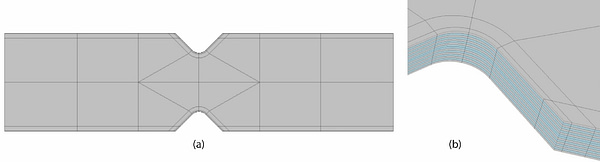
Figure 1: (a) Finite element mesh consisting of 832 thin solid elements. (b) Detail.
The material is an IM7/8551-7A prepreg with a [±45°]4s layup. The laminate stack is shown in Figure 1(b). The material properties are listed in Table 1. The specimen is loaded by uniform tension. The goal is to estimate whether conditions for failure initiation exist, given Hashin’s failure criteria [7]. To illustrate an application of the hp-version to this class of problems, it is sufficient to consider only one of the criteria. We will use the Fiber Tension Failure Index for this purpose:
F_{tf} = \left(\frac{\sigma_{11}}{X_{t}} \right)^2 + \left(\frac{\tau_{12}}{S} \right)^2, \qquad \sigma_{11}\ge 0where the indices 1 and 2 indicate the directions parallel and normal to the fiber, respectively, Xt is the longitudinal tensile strength and S is the in-plane shear strength. Here we will use Xt = 2758 MPa and S = 90 MPa.
Table 1: Elastic material properties
| Elastic moduli (GPa) | E11 = 162 | E22 = 8.9 | E33 = 8.9 |
| Poisson’s ratios | ν12 = 0.30 | ν23 = 0.46 | ν13 = 0.30 |
| Shear moduli (GPa) | G12 = 5.17 | G23 = 3.03 | G13 = 5.17 |
The finite element mesh, consisting of 832 hexahedral elements, and the Hashin Fiber Tension Failure (FTF) Index Ftf are shown in Figure 1. The mesh was designed considering a priori information about the exact solution of the elasticity problem: Laminated composites typically have strong boundary-layer effects; therefore, the mesh must be strongly graded at the boundary. The hp version of the finite element method supports large aspect ratios, making it well suited for treating laminated composite problems.
As shown in Figure 2, the Hashin FTF index spikes sharply within a narrow boundary region near the notch root. This localization is a direct consequence of the boundary layer effect. To relate these continuum-mechanics results to the strength response of real materials, microstructural heterogeneity must be taken into account. Consequently, pointwise stresses and strains are not representative and must instead be evaluated as averages over a volume at least as large as the Representative Volume Element (RVE).
There are various possibilities for defining averaging methods. The relative merit of competing definitions is evaluated by ranking their predictive performance using experimental information. One such averaging method, known as the Average Stress Criterion (ASC), was proposed by Whitney and Nuismer [8]. In the ASC, stress components are averaged over an experimentally determined characteristic length, which is assumed to be a material property. An alternative approach is based on a volume integral:
G_{tf} = \frac{1}{V_{c}} \int_{\Omega_c}^{} F_{tf} \,dV\,, \qquad \sigma_{11}\ge 0 \qquad \qquad (2a)where Ωc is the domain of integration and Vc is the volume of Ωc. In the case of linear mapping,
\Omega_{c} = \Bigl\{\textbf{x} | \textbf{x}\in L_x \times L_y \times t_{ply} \Bigr\} \qquad \qquad \qquad (2b)Here, x is the position vector, Lx, Ly are length parameters, determined by calibration, and tply is the ply thickness. For curved elements, care must be taken to preserve a strictly constant averaging volume and a uniform length scale along the curved boundaries. See the inset in Figure 2.
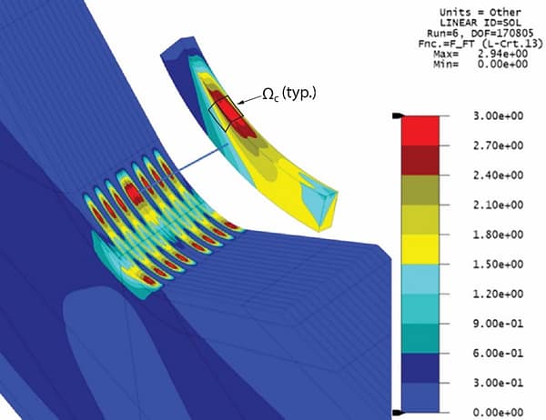
Figure 2: Boundary layer effects at the notch root. Contours of Hashin’s Fiber Tension Failure Index.
Takeaways
- The stress field associated with the linearly elastic solution serves as a reference solution for calibrating failure criteria. Because the parameters of these criteria are inferred from experimental observations, accurate interpretation of such experiments requires a method capable of delivering verified stress fields. Therefore, solution verification is an essential technical requirement for the reliable calibration and application of failure criteria.
- The primary challenge in the numerical simulation of laminated composites is controlling both the discretization and model-form errors. Conventional laminated plate and shell formulations incorporate restrictive assumptions concerning the through-thickness behavior of the laminate. While these assumptions can yield computationally efficient models for structural analysis, they are poorly suited for strength predictions.
- The hp-version of the finite element method offers a fundamentally different framework. By employing thin solid elements and independent polynomial enrichments (p-extensions) in the in-plane and through-thickness directions, it enables discretization and model-form errors to be controlled separately. Convergence can be monitored explicitly, allowing analysts to determine whether additional refinement is needed and where to apply it. As a result, the method provides a practical pathway to obtain verified stress fields and, consequently, improve the reliability of strength predictions in laminated composites.
References
[1] Szabó, B. and Babuška, I. (2021). Finite Element Analysis. Method, Verification and Validation. 2nd Edition. John Wiley & Sons Inc. New York.
[2] Reddy, J. N. (2004). Mechanics of Laminated Composite Plates and Shells: Theory and Analysis (2nd Edition), CRC Press.
[3] Carrera, E. (2002). “Theories and finite elements for multilayered, anisotropic, composite plates and shells.” Archives of Computational Methods in Engineering, 9(2), pp. 87-140.
[4] Mittelstedt, C., Becker, W., Kappel, A. and Kharghani, N. (2022). Free-edge effects in composite laminates—a review of recent developments 2005–2020. Applied Mechanics Reviews, 74(1), p. 010801.
[5] Kaddour, A.S. and Hinton, M.J. (2013). The Second-World-Wide Failure Exercise (WWFE-II): Part B: Evaluation of Theories for Predicting Failure in Polymer Composite Laminates Under 3-D States of Stress: Comparison with experiments. Journal of Composite Materials, 47(6-7).
[6] Szabó, B. and Actis, R. The demarcation problem in the applied sciences. Computers & Mathematics with Applications, 162, pp. 206-214, 2024.
[7] Hashin, Z. (1980). Failure criteria for unidirectional fiber composites. Journal of Applied Mechanics, 47(2), pp. 329–334.
[8] Whitney, J.M. and Nuismer, R.J. (1974). Stress fracture criteria for laminated composites containing stress concentrations. Journal of composite materials, 8(3), pp. 253-265.
Related Blog Posts:
- A Memo from the 5th Century BC
- Obstacles to Progress
- Why Finite Element Modeling is Not Numerical Simulation?
- XAI Will Force Clear Thinking About the Nature of Mathematical Models
- The Story of the P-version in a Nutshell
- Why Worry About Singularities?
- Questions About Singularities
- A Low-Hanging Fruit: Smart Engineering Simulation Applications
- The Demarcation Problem in the Engineering Sciences
- Model Development in the Engineering Sciences
- Certification by Analysis (CbA) – Are We There Yet?
- Not All Models Are Wrong
- Digital Twins
- Digital Transformation
- Simulation Governance
- Variational Crimes
- The Kuhn Cycle in the Engineering Sciences
- Finite Element Libraries: Mixing the “What” with the “How”
- A Critique of the World Wide Failure Exercise
- Meshless Methods
- Isogeometric Analysis (IGA)
- Chaos in the Brickyard Revisited
- Why Is Solution Verification Necessary?
- Variational Crimes and Refloating the Costa Concordia
- Lessons From a Failed Model Development Project
- Where Do You Get the Courage to Sign the Blueprint?
- Great Expectations: Agentic AI in Mechanical Engineering
- The Differences Between Calibration and Tuning
- Honored in the Breach
- Remembering Ivo Babuška
- Turtle Shells and Legacy Finite Element Codes: Evolutionary Constraints in the Age of Explainable AI
- Beyond the Black Box: Explainable AI Requires Explainable Simulation
- Trustworthiness in Simulation: Credibility or Decision-grade Reliability?
- From Finite Element Modeling to Simulation Science: Unlocking the Power of Numerical Simulation







Leave a Reply
We appreciate your feedback!
You must be logged in to post a comment.